The following topic is now open for discussion: Electric fields, potentials, capacitors and parallel plates
If you have a question regarding this topic, please post a comment to this post by clicking on the comment link below.
04 February 2008


Electric fields and electrostatic potential
I've had an interesting discussion regarding Electric field and Electric potential and thought I would repost it here so it wasn't buried in the comments of an old post...
In relation to the post Question: E=V/d or V=-Ed? (to minus or not to minus), Peter asked:
Which is exactly right. In fact, the "full" form (using vector calculus) is given by:

which essentially says to add up (integrate) the components of the electric field parallel to the path taken (the dl). If the electric field is constant and the path is straight, then everything reduces to what we have above.
Conversely, the electric field is proportional to a sort of directional slope of the potential (called the gradient) such that the greatest forces will be felt by charges in the "steepest" regions of electrostatic potential. More on that later perhaps...
In relation to the post Question: E=V/d or V=-Ed? (to minus or not to minus), Peter asked:
Hey, I was just reading Cutnell & Johnson Physics 7th edition (Competitor textbook to Giancoli) and on pg 585 it had some comments about this. I am not sure if it is applicable?
They first derived the -form of the equation. So they said
W = Fd =qEd
But W = -PE
qEd = -PE
qEd/q = -PE/q
Ed = -V
V = -Ed
Ok so far so good.
then they had some comments about the form of the equation where V = Ed (no negative sign)
"When applied strictly to a parallel plate capacitor, however, this expression is often used in a slight different form. In figure 19.16, the metal plates of the capacitor are marked A( higher potential) and B (lower potential). Traditionally, in discussions of such a capacitor, the potential difference between the plates is referred to by using the symbol V to denote the amount by which the higher potential exceeds the lower potential. V = Va-Vb.
Thus,
E = -V/d = - (Vb-Va)/d = (Va-Vb)/d = V/d.
Would this be a valid explanation as well since in this course we are mostly dealing with parallel plate capacitors? Thanks.
Hi Peter,
Excellent idea to check out another text book, sometimes a different perspective is all you need...
However, I disagree with Cutnell's approach here. They are essentially taking advantage of two negatives which cancel, and I think it is confusing. It is true that, as a sort of shorthand, the potential difference between the plates is simply given as the amount by which the higher potential exceeds the lower. The problem I see with using this "no minus" version of the equation is that it does not represent the true relationship between E and V (ie. that the electric field points from the high potential to the low potential). This takes a relationship and turns it into an equation, which I dislike. Equations are limited in scope and easy to misapply, relationships can give you better understanding which is a much more solid basis.
I'd rather see you sketch a diagram showing the high and low potential and where the positive and negative charges are separated on the two plates and applying the "V" given as the magnitude of the potential difference. It will be much harder to go wrong with this picture in front of you, and the whole "-" issue more or less disappears.
I hope that helps.
Gee you are totally right. I posted this early this morning and now I already have a different idea, which you have already hinted here but I want to make sure I got this down 100%.
This just came to me. 
Is this way of thinking correct?
Thanks!
Which is exactly right. In fact, the "full" form (using vector calculus) is given by:

which essentially says to add up (integrate) the components of the electric field parallel to the path taken (the dl). If the electric field is constant and the path is straight, then everything reduces to what we have above.
Conversely, the electric field is proportional to a sort of directional slope of the potential (called the gradient) such that the greatest forces will be felt by charges in the "steepest" regions of electrostatic potential. More on that later perhaps...
29 January 2008
Topic open: Electric Potential and Potential Energy
The following topic is now open for discussion: Electric Potential and Potential Energy.
If you have a question regarding this topic, please post a comment to this post by clicking on the comment link below.
If you have a question regarding this topic, please post a comment to this post by clicking on the comment link below.
10 January 2008
Topic open: Forces on charges and Electric fields
The following topic is now open for discussion: Forces on charges and Electric fields.
If you have a question regarding this topic, please post a comment to this post by clicking on the comment link below.
If you have a question regarding this topic, please post a comment to this post by clicking on the comment link below.
New Example! Chapter 16 #15
Now posted on the main WebTA site:
Chapter 16, #15
Before heading over to check it out, I suggest you try it yourself and then take a look.
Chapter 16, #15
Before heading over to check it out, I suggest you try it yourself and then take a look.
07 January 2008
Welcome to the physics 102 webTA blog: winter '08
Welcome back to a new term!
I will be continuing as the webTA for physics 102 for the 3rd time now. As with every other year, I hope that I can continue to make this online resource more and more useful. If you have any thoughts or suggestions on how to improve the online materials, I am always open to suggestions. You can contact me through the blog, discussions or by email (webta101 at physics.mcgill.ca) with your ideas.
This year the webTA persona will take on three aspects:
For the sake of my email inbox, I will ask you to refrain from emailing me questions. Instead, I suggest you either post your question to the discussion boards (where you may find a friend will answer before I get a chance!) or post your question in one of the "topic open" posts as a comment on the blog. There are a few groundrules for asking questions that I suggest you check before asking. This has worked out for two years so far, so let's try to stick with it. Also, while the WebCT discussion board will always leave your name, anything posted to the blog will remain anonymous. You can post questions here anonymously and when I post answers I will never include your name. I hope this encourages you to ask any question you want even if you might feel it is "stupid". Often those solve the most trouble and end up being the most worthwhile.
One great thing about you being the 3rd year to have access to this is that there is a considerable compilation of previous students' question now on the blog. I'm hoping to move a few of these examples over to the static site, but for now if you are having a problem I suggest you check backposts of the blog for possible answers. I've tried to label all the posts with their relevant topics and a list is available in the sidebar under "post topics". You can also use the search bar at the top and hit "search blog" to search within the archives. You may not find exactly what you are looking for, but it might give you a starting point, and a better place to start asking questions.
A couple more things: I may (likely) not be able to answer every single question (the webTA is a single person, me, and not a collection of TA's and I only have so many hours to work on this). My strategy in the past has been to post about the most common problems (eg: 2 people ask about the same problem, and someone else asks about a related concept). This means that you can't solely rely on the webTA for help. Which brings me to my other point: I hope that you will see this as an additional resource and not a replacement for the regular tutorials. It is often easier to sit down face-to-face with a real TA to work out what you are having trouble with. Make use of whatever resources you need.
Good luck, and I look forward to a good semester working with you!
Sarah :)
I will be continuing as the webTA for physics 102 for the 3rd time now. As with every other year, I hope that I can continue to make this online resource more and more useful. If you have any thoughts or suggestions on how to improve the online materials, I am always open to suggestions. You can contact me through the blog, discussions or by email (webta101 at physics.mcgill.ca) with your ideas.
This year the webTA persona will take on three aspects:
- the static site with examples and explanations
- this blog, where answers to your most common questions will be answered in some detail
- the WebCT discussion forum, to provide a more interactive environment for providing answers
For the sake of my email inbox, I will ask you to refrain from emailing me questions. Instead, I suggest you either post your question to the discussion boards (where you may find a friend will answer before I get a chance!) or post your question in one of the "topic open" posts as a comment on the blog. There are a few groundrules for asking questions that I suggest you check before asking. This has worked out for two years so far, so let's try to stick with it. Also, while the WebCT discussion board will always leave your name, anything posted to the blog will remain anonymous. You can post questions here anonymously and when I post answers I will never include your name. I hope this encourages you to ask any question you want even if you might feel it is "stupid". Often those solve the most trouble and end up being the most worthwhile.
One great thing about you being the 3rd year to have access to this is that there is a considerable compilation of previous students' question now on the blog. I'm hoping to move a few of these examples over to the static site, but for now if you are having a problem I suggest you check backposts of the blog for possible answers. I've tried to label all the posts with their relevant topics and a list is available in the sidebar under "post topics". You can also use the search bar at the top and hit "search blog" to search within the archives. You may not find exactly what you are looking for, but it might give you a starting point, and a better place to start asking questions.
A couple more things: I may (likely) not be able to answer every single question (the webTA is a single person, me, and not a collection of TA's and I only have so many hours to work on this). My strategy in the past has been to post about the most common problems (eg: 2 people ask about the same problem, and someone else asks about a related concept). This means that you can't solely rely on the webTA for help. Which brings me to my other point: I hope that you will see this as an additional resource and not a replacement for the regular tutorials. It is often easier to sit down face-to-face with a real TA to work out what you are having trouble with. Make use of whatever resources you need.
Good luck, and I look forward to a good semester working with you!
Sarah :)
16 April 2007
Good Luck and signing off!
Your friendly neighbourhood webTA here wishing you good luck on your exam tomorrow! Wise advice from Douglas Adams and the Hitchiker's Guide to the Galaxy:
DON'T PANIC!
Relax, try to stay clear-headed, and don't stay up all night studying, get some sleep.
Good luck to you all.
DON'T PANIC!
Relax, try to stay clear-headed, and don't stay up all night studying, get some sleep.
Good luck to you all.
05 April 2007
Question: AC circuits and resonance
This question relates to Lab 6 but also to the lecture material (it was in the lab that I figured out that my understanding of the material was totally wrong).
It makes sense that in an A/C circuit the capacitor charges when there is a voltage and then discharges through the inductor when the voltage goes away. Also, it seems that the capacitor may or may not reach it's max charge depending of the frequency of the A/C generator (is that correct?). But why does the charging/discharging create a pattern with deteriorating voltage? It seems like the charge in the capacitor should just go up and down to the same extream values over and over. And how is this related to the resonance of the circuit at all? For some reason the frequency of these oscillations is the same as the resonance frequency, but it seems like this shouldn't be the case at all, I would have thought they would be very different values.
Let's see if I can help...
Your first comment is regarding the decay in the oscillations in the LC circuit. It's been awhile since I was a lab demonstrator, so I don't recall the setup exactly for this experiment, however, it sounds like there is a resistance in the circuit (whether there is a resistor there or not... it could be the fact that you have a "real" inductor which consists of a length of wire and will have some resistance). In that case, you have a damped harmonic oscillator system. The inductor and capacitor act as an oscillator (where the capacitor acts like a mass, and the inductor provides a restoring force like a spring), but the resistance provides a means for energy to leave the system, so the oscillations will decay. An analogous mechanical system would be a mass on a spring in molasses... for an entertaining visual. As for what you think it "should" do, you are correct, in that if you had a perfect capacitor and a perfect inductor with no resistances, the system would keep on oscillating forever.
As for resonance... this seems to confuse a lot of people every year. Here's a question and answer from a couple of years ago just to define what we are talking about:
Q: I am a little confused about frequency. What exactly is the resonant frequency and how and why does it effect the current compared to the frequency?
A: In an AC circuit, depending on the components in the circuit, the impedance (a sort of complex resistance) may depend on the frequency. Thus, if an oscillating voltage is applied, the amplitude of the current (peak amount of current that flows) may also depend on the frequency of the applied voltage. This is how the current depends on frequency.
In the case of an LRC circuit, there is a phenomenon called "resonance", whereby the amplitude response of the current has a maximum at the so-called "resonant frequency". Resonance is a common in oscillatory systems, where the amplitude response of the system, be it a mechanical system, or an electrical system, has a maximum at some frequency. At frequencies other than the resonance frequency the amplitude response of the system (the amplitude of the current in this case) will be smaller.
Now, in an electrical system, the resonance will be established by the capacitor and the inductor (the resistance provides the damping), and the values of these components will give the resonance frequency, which is the natural frequency at which the oscillating system operates at, and where it will have the greatest response if you drive it with a frequency. If you input an oscillating voltage to an LC circuit, the amplitude of the current should be very small until you get near the resonance frequency. However... I'm not sure if this is what you did?
If you input a square wave at a much much lower frequency than the resonance, then it will be like turning on and off the voltage, and you would see oscillations at the resonance frequency, which would decay until the next cycle when they would start again. Perhaps this is what you did in the lab.
I hope this is somewhat helpful. Without knowing what you did in lab, I can't be sure where the confusion lies. Please do comment (click the # comment link below... or email if that doesn't work) to follow up!
It makes sense that in an A/C circuit the capacitor charges when there is a voltage and then discharges through the inductor when the voltage goes away. Also, it seems that the capacitor may or may not reach it's max charge depending of the frequency of the A/C generator (is that correct?). But why does the charging/discharging create a pattern with deteriorating voltage? It seems like the charge in the capacitor should just go up and down to the same extream values over and over. And how is this related to the resonance of the circuit at all? For some reason the frequency of these oscillations is the same as the resonance frequency, but it seems like this shouldn't be the case at all, I would have thought they would be very different values.
Let's see if I can help...
Your first comment is regarding the decay in the oscillations in the LC circuit. It's been awhile since I was a lab demonstrator, so I don't recall the setup exactly for this experiment, however, it sounds like there is a resistance in the circuit (whether there is a resistor there or not... it could be the fact that you have a "real" inductor which consists of a length of wire and will have some resistance). In that case, you have a damped harmonic oscillator system. The inductor and capacitor act as an oscillator (where the capacitor acts like a mass, and the inductor provides a restoring force like a spring), but the resistance provides a means for energy to leave the system, so the oscillations will decay. An analogous mechanical system would be a mass on a spring in molasses... for an entertaining visual. As for what you think it "should" do, you are correct, in that if you had a perfect capacitor and a perfect inductor with no resistances, the system would keep on oscillating forever.
As for resonance... this seems to confuse a lot of people every year. Here's a question and answer from a couple of years ago just to define what we are talking about:
Q: I am a little confused about frequency. What exactly is the resonant frequency and how and why does it effect the current compared to the frequency?
A: In an AC circuit, depending on the components in the circuit, the impedance (a sort of complex resistance) may depend on the frequency. Thus, if an oscillating voltage is applied, the amplitude of the current (peak amount of current that flows) may also depend on the frequency of the applied voltage. This is how the current depends on frequency.
In the case of an LRC circuit, there is a phenomenon called "resonance", whereby the amplitude response of the current has a maximum at the so-called "resonant frequency". Resonance is a common in oscillatory systems, where the amplitude response of the system, be it a mechanical system, or an electrical system, has a maximum at some frequency. At frequencies other than the resonance frequency the amplitude response of the system (the amplitude of the current in this case) will be smaller.
Now, in an electrical system, the resonance will be established by the capacitor and the inductor (the resistance provides the damping), and the values of these components will give the resonance frequency, which is the natural frequency at which the oscillating system operates at, and where it will have the greatest response if you drive it with a frequency. If you input an oscillating voltage to an LC circuit, the amplitude of the current should be very small until you get near the resonance frequency. However... I'm not sure if this is what you did?
If you input a square wave at a much much lower frequency than the resonance, then it will be like turning on and off the voltage, and you would see oscillations at the resonance frequency, which would decay until the next cycle when they would start again. Perhaps this is what you did in the lab.
I hope this is somewhat helpful. Without knowing what you did in lab, I can't be sure where the confusion lies. Please do comment (click the # comment link below... or email if that doesn't work) to follow up!
18 March 2007
Question: Induced EMF coil-solenoid; How do areas play a role?
If a coil is placed around a solenoid that has a fluctuating current, how do the radii of the coil and solenoid (so basically, the areas) affect the induced EMF in the coil? Thanks.
Thanks for your question.
The EMF induced in the outer coil is a result of the magnetic field produced in the solenoid.
First let's consider the magnetic field produced by the solenoid, which is given by:
B=μnl
where n is the number of turns/unit length. But wait! There's no mention of area here... in fact as long as the approximation that l>>r holds (and that you are not near the ends), the magnetic field generated by a solenoid is independent of the cross-sectional area.
So let's consider the EMF induced in the coil surrounding the solenoid. This is given by:
EMF=-ΔΦB/Δt=-AperpendicularΔB/Δt
So the cross-sectional area of the coil does enter into the induced EMF.
Hope that is helpful. For a related question check out: Question: Solenoid in a coil
Thanks for your question.
The EMF induced in the outer coil is a result of the magnetic field produced in the solenoid.
First let's consider the magnetic field produced by the solenoid, which is given by:
B=μnl
where n is the number of turns/unit length. But wait! There's no mention of area here... in fact as long as the approximation that l>>r holds (and that you are not near the ends), the magnetic field generated by a solenoid is independent of the cross-sectional area.
So let's consider the EMF induced in the coil surrounding the solenoid. This is given by:
EMF=-ΔΦB/Δt=-AperpendicularΔB/Δt
So the cross-sectional area of the coil does enter into the induced EMF.
Hope that is helpful. For a related question check out: Question: Solenoid in a coil
06 March 2007
Topic open: Magnetostatics
The following topic is now open for questions: Magnetostatics.
To pose a question, please post a comment to this post by clicking on the comments link below.
To pose a question, please post a comment to this post by clicking on the comments link below.
Topic open: Circuits
The following topic is now open for questions: Circuits. Anything about resistors, capacitors, RC, RL, RLC circuits.
To pose a question, please post a comment to this post by clicking on the comments link below.
To pose a question, please post a comment to this post by clicking on the comments link below.
31 January 2007
"Potential" for confusion: Electrostatic potential and potential energy
Let's start at the beginning:
Electric Potential Energy, like any other potential energy, is defined in relation to a conservative force: in this case, the electrostatic force. If one moves a charge from one point to another through an electric field, one must exert a force over this distance... hence work has been done, which corresponds to a difference in the potential energy.
The electric PE at a given point is generally defined relative to a point at infinity; ie. infinitely far away from the influence of any other charges. This is why we talk about "bringing charges in from infinity" to calculate the potential energy of an arrangement of charges.
One additional complication with electric potential energy compared to graviational potential energy is that charges have different signs. That means that the forces which lead to the potential energy can be either attractive or repulsive. It is perhaps worth drawing from the vector definintion of work:
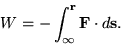
which tells us that we consider only the contributions of the force which are parallel (or antiparallel) to the path. The result? If we are moving the particle on a path parallel to the force on that particle (the force is acting in the same direction we are moving the particle), the work done by the force will be positive, and the potential energy will decrease. Since we are starting at infinity where the PE is zero, this means we will end up with a negative PE. Conversely, if we are moving the particle in countering the force (the force and direction are anti-parallel) then the resulting PE will be positive.
In this way we can think of PE around charges as hills and valleys: if the force between the "active" particle and another in the arrangement is attractive we will have a potential energy valley, but if the force is repulsive we have a potential energy hill. Let's hold onto this landscape idea and revisit it in relation to electric potential.
Electric, or electrostatic, Potential is the electrostatic potential per unit charge. Think of it as: electric potiential is to electrostatic PE, as electric field is to electrostatic force. That means that the electric potential takes on all the same characteristics as the electrostatic potential: it is a scalar quantity, it can be positive or negative depending on whether the interaction is repulsive or attractive.
Like the electric field, the sign will be determined by considering a positive test charge. With electric field, the direction of the vector quantity is determined by the direction of a force on a positive test charge. Since electric potential doesn't have a direction, it is just the sign which is determined by the positive test charge.
Let's return to our landscape idea then... with PE, we have to consider the magnitude and sign of the charge we are describing, however, since electric potential is per unit charge, it will always remain the same (unless the charges defining the landscape move). Since the positive test charge will be attracted by negative charges, there will be "valleys", or regions of negative potential near these, and near positive charges there will be "hills", or regions of positive potential. In this way, electric potential is kind of a measure of the attractiveness and repulsiveness of a position... just remember that it will be opposite for a negative charge.
I hope I've helped, and not muddled the situation further. Please post a comment if you wish some clarification.
I have some other resources posted for you on the topic of electric potential and potential energy for further reading:
Electric Potential Energy, like any other potential energy, is defined in relation to a conservative force: in this case, the electrostatic force. If one moves a charge from one point to another through an electric field, one must exert a force over this distance... hence work has been done, which corresponds to a difference in the potential energy.
The electric PE at a given point is generally defined relative to a point at infinity; ie. infinitely far away from the influence of any other charges. This is why we talk about "bringing charges in from infinity" to calculate the potential energy of an arrangement of charges.
One additional complication with electric potential energy compared to graviational potential energy is that charges have different signs. That means that the forces which lead to the potential energy can be either attractive or repulsive. It is perhaps worth drawing from the vector definintion of work:
which tells us that we consider only the contributions of the force which are parallel (or antiparallel) to the path. The result? If we are moving the particle on a path parallel to the force on that particle (the force is acting in the same direction we are moving the particle), the work done by the force will be positive, and the potential energy will decrease. Since we are starting at infinity where the PE is zero, this means we will end up with a negative PE. Conversely, if we are moving the particle in countering the force (the force and direction are anti-parallel) then the resulting PE will be positive.
In this way we can think of PE around charges as hills and valleys: if the force between the "active" particle and another in the arrangement is attractive we will have a potential energy valley, but if the force is repulsive we have a potential energy hill. Let's hold onto this landscape idea and revisit it in relation to electric potential.
Electric, or electrostatic, Potential is the electrostatic potential per unit charge. Think of it as: electric potiential is to electrostatic PE, as electric field is to electrostatic force. That means that the electric potential takes on all the same characteristics as the electrostatic potential: it is a scalar quantity, it can be positive or negative depending on whether the interaction is repulsive or attractive.
Like the electric field, the sign will be determined by considering a positive test charge. With electric field, the direction of the vector quantity is determined by the direction of a force on a positive test charge. Since electric potential doesn't have a direction, it is just the sign which is determined by the positive test charge.
Let's return to our landscape idea then... with PE, we have to consider the magnitude and sign of the charge we are describing, however, since electric potential is per unit charge, it will always remain the same (unless the charges defining the landscape move). Since the positive test charge will be attracted by negative charges, there will be "valleys", or regions of negative potential near these, and near positive charges there will be "hills", or regions of positive potential. In this way, electric potential is kind of a measure of the attractiveness and repulsiveness of a position... just remember that it will be opposite for a negative charge.
I hope I've helped, and not muddled the situation further. Please post a comment if you wish some clarification.
I have some other resources posted for you on the topic of electric potential and potential energy for further reading:
23 January 2007
Topic open: Electric Potential and Potential Energy
The following topic is now open for questions: Electrostatic Potential and Potential Energy.
To pose a question, please post a comment to this post by clicking on the comments link below.
To pose a question, please post a comment to this post by clicking on the comments link below.
19 January 2007
Vector Addition
Since many of you seem a little uncertain about adding vectors, here's a quick review example:

The proceedure is the same when you have more than two vectors. Break down all the vectors into components relative to some coordinate system (note that you can choose this such that it is aligned with one of your vectors), add all the components and then using the pythagorean theorem find the magnitude of the resultant vector, and find the angle using trigonometry.

The proceedure is the same when you have more than two vectors. Break down all the vectors into components relative to some coordinate system (note that you can choose this such that it is aligned with one of your vectors), add all the components and then using the pythagorean theorem find the magnitude of the resultant vector, and find the angle using trigonometry.
09 January 2007
Topic open: Forces on charges and Electric fields
The following topic is now open for discussion: Forces on charges and Electric fields.
If you have a question regarding this topic, please post a comment to this post by clicking on the comment link below.
If you have a question regarding this topic, please post a comment to this post by clicking on the comment link below.
Subscribe to:
Posts (Atom)

